Well Pattern Design
Generated wells
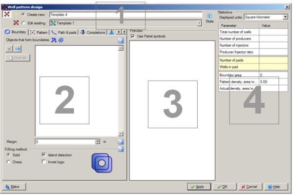
Click Make button located in the bottom left corner of the window to create new wells.
Plug-in Overview
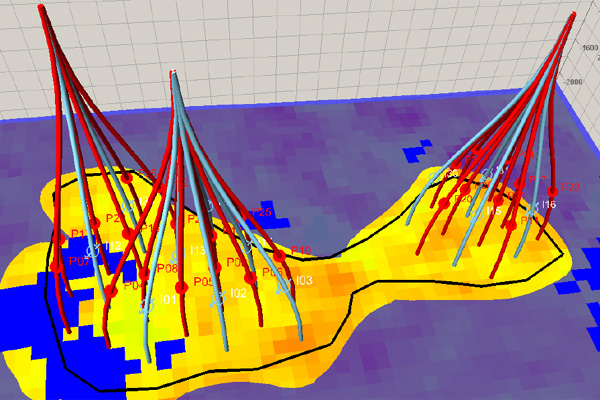
The ability to use reservoir models to simulate different scenarios for Field Development Planning is a common approach for making decisions about well pattern design, pattern orientation and well spacing. To minimize the risks associated with making these decisions the simulation is often run hundreds of times and the results are analyzed to choose the optimal (lowest risk) field development scenario. The current approach is to manually create the different well placement scenarios and run the simulations under those scenarios. This is a tedious and lengthy process and is based on user discretion. The Well Pattern plug-in automates the creation of these different scenarios which then greatly reduces the time it takes to prepare the different cases needed for the reservoir simulation.
Specifications
- The area of interest is allowed to be defined either as single, closed polygon or as the complex polygons’ set intersection, surface or point set.
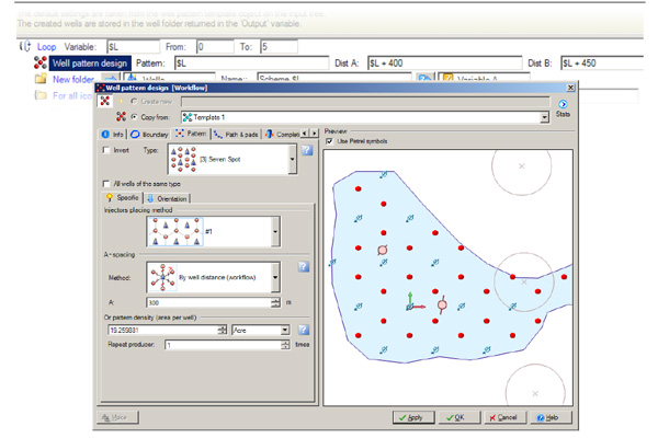
- The pattern scheme is selected from predefined set of common FDP practice patterns: line drive (either direct or staggered with desired amount of producer rows), spot (5-, 7-, 9- and 13-spot patterns either normal or inverted) and generic producers’ pattern.
- The completion types available are open hole (no casing must be added to wells) and perforation. It is possible to specify perforation interval in several manners: within constant depth, between surfaces, by threshold property value. Optionally those wells, which have no connections with grid, may be eliminated from pattern automatically.
- Simple drilling schedule algorithm is supported by custom setting the number of available rigs, start date, drilling time per each well and time to move rig between pads.
- The pattern design framework allows user to specify exclusion zones (non-drilling circle areas around existing wells) as wells, well folders, well markers or well tops.
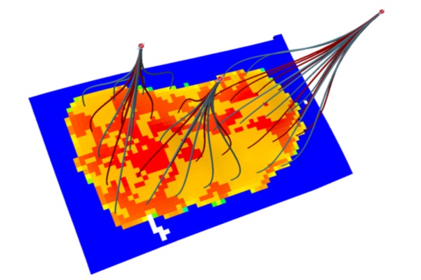
- The well trajectories are to be created according pad map specified either by point set or by polygon within defined depth interval (top and bottom limits) and with appointed wellhead distance and rig direction azimuth.
- The visualization options allow customizing the well symbols and colors and setting well name template with wildcard characters for producer and injector separately.
- The result destination folder may be either defaulted (“Wells” folder in Petrel project “Input” pane) or specified from “Input” pane in combination with simple grouping rules.
- Brief description is presented on “Info” tab of the process main window. Full user guide is available separately in PDF format.
Features
- Utilize Petrel to quickly create different well patter


